Tutorial: How to Make a Symmetric Brain Image
By Rui Gong, Connectome Analysis Unit.
Introduction
This tutorial will teach the user how to remove asymmetry in brain data, creating a symmetric brain where the left and right hemispheres appear the same. We will use a combination of Python scripts and the Advanced Normalization Tools (ANTs).
Why Make a Symmetric Brain Image?
Making manual brain annotations can be a difficult and time consuming process. For species that have no obvious lateralization, annotations can be made on a single hemisphere and mirrored into the other. Conversely, mapping data with a symmetric reference brain can allow us to discover any asymmetries in individual data.
A hemisphere symmetric atlas can also be useful to simplify computations when processing data and comparing hemispheres. For example, our latest Brain/MINDS atlas (BMA 2023) is a symmetric one and can be viewed here.
When making a reference or average brain, we can convert asymmetric data into symmetric data, making it easier to map it with new data and to make sure all brain structures are represented equally.
ANTs and Python Installation
ANTs
The latest release of ANTs can be found on the official github page.
This tutorial uses ANTs v2.5.0 (Eurymyrmex).
- If your platform is a popular one, you may directly download the binaries package containing the compiled version of ANTs in the
Assetssection within the release github page.
Please follow the installation instructions to properly install the binaries package.
- In case there is no binaries package for your platform, you’ll have to compile ANTs from sources.
Please follow the guide to compile and install ANTs for Linux/MacOS or Windows.
Python
We used Python Version 3.7.1.1 in this tutorial.
Compatible versions of SimpleITK and NumPy packages for Python must be installed as well. We recommend to set up an isolated Python virtual environment for the tutorial, as described in this Visual Studio Code documentation (terminal command instructions can be used even if you’re not using VS Code as your Python IDE).
Download Sample Data
In this tutorial we will use the file T2WI_ex001.nii.gz from eNA91 (Ex Vivo) dataset (see Marmoset MRI NA216 Dataset page).
The file can be downloaded from Dataportal GIN server by typing the following commands in a terminal :
wget https://datasets.brainminds.jp/brainminds/MRI_NA216/media/master/exvivo/e_T2WI/T2WI_ex001.nii.gz
Tutorial steps
Step 1 : Flip the Original Brain Across the Sagittal Plane
To flip the brain, please run the following Python code:
import SimpleITK as sitk
import numpy as np

img = sitk.ReadImage('T2WI_ex001.nii.gz')
imgNda = sitk.GetArrayFromImage(img)

imgNda = np.flip(imgNda, 2)

out = sitk.GetImageFromArray(imgNda)
out.CopyInformation(img)

sitk.WriteImage(out, 'T2WI_ex001_flip.nii.gz')
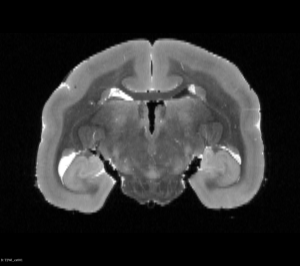
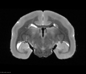
You can view Nifti files before and after the flip using tools such as ITK-SNAP or 3D Slicer as shown below:
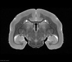
Original T2WI MRI Brain (Coronal View)
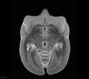
Original T2WI MRI Brain (Axial View)
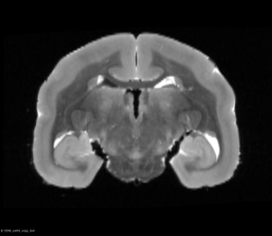
Original T2WI MRI Brain (Coronal View)
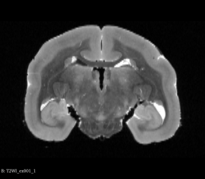
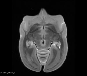
Flipped T2WI MRI Brain (Axial View)
Step 2: Register Flipped Brain to Original Brain
Run the following command using ANTs to register the flipped brain to the original brain:
antsRegistrationSyNQuick.sh -d 3 \
   -f T2WI_ex001.nii.gz \
   -m T2WI_ex001_flip.nii.gz \
   -o T2WI_ex001_reg_ \
   -n 8
Lets go over each arguments in the above command:
| Argument | Value | Explanation |
|---|---|---|
| -d | 3 | This is the dimension, since we are working with 3D volumes, the dimension is 3. |
| -f | T2WI_ex001.nii.gz | This is the fixed image or the image we want to register to, in our case, this will be original T2WI MRI brain. |
| -m | T2WI_ex001_flip.nii.gz | This is the moving image or the image we want to register, in our case, this will be the flipped T2WI MRI brain from Step 1. |
| -o | T2WI_ex001reg | This is the output prefix, in this example, the output files will all have the prefix ”T2WI_ex001reg” |
| Optional argument | ||
| -n | 8 | This is the number of threads to use during registration to speed things up. Here, we use 8 threads. |
The above step should output the following 5 files:
| File name | Description |
|---|---|
| T2WI_ex001_reg_0GenericAffine.mat | This is the output for affine transform. |
| T2WI_ex001_reg_1InverseWarp.nii.gz | This is the output for inverse displacement field. |
| T2WI_ex001_reg_1Warp.nii.gz | This is the output for displacement field. |
| T2WI_ex001_reg_InverseWarped.nii.gz | This is the result of original brain registered to flipped brain. |
| T2WI_ex001_reg_Warped.nii.gz | This is the result of flipped brain registered to the original brain. |
Step 3: Combine Affine and Displacement Fields
Run the following commands using ANTs to combine transformation files from Step 2 to be used in the next step:
To combine transforms of flipped brain to original brain
ComposeMultiTransform 3 \
   outcompose_fwd.nii.gz \
   -R T2WI_ex001.nii.gz \
   T2WI_ex001_reg_0GenericAffine.mat \
   T2WI_ex001_reg_1Warp.nii.gz
The above command takes positional parameters as described below (in order, from left to right):
| Value | Explanation |
|---|---|
| 3 | The 1st argument is the dimension, since we are working with 3D volumes, the dimension is 3. |
| outcompose_fwd.nii.gz | The 2nd argument is the output file name |
| -R T2WI_ex001.nii.gz | The 3rd argument is the reference image we used for registration, in this case, it is the original average T2WI MRI brain. |
| T2WI_ex001_reg_0GenericAffine.mat | The 4th and 5th are the transformations we want to combine. Here the order is very important, as transformations are applied from right to left. Here, we apply the displacement field first then the affine transforms to go from flipped brain to original brain. |
| T2WI_ex001_reg_1Warp.nii.gz |
To combine transforms of original brain to flipped brain
ComposeMultiTransform 3 \
   outcompose_bck.nii.gz \
   -R T2WI_ex001.nii.gz \
   T2WI_ex001_reg_1InverseWarp.nii.gz \
   -i T2WI_ex001_reg_0GenericAffine.mat
The above command takes positional parameters as described below (in order, from left to right):
| Value | Explanation |
|---|---|
| 3 | The 1st argument is the dimension, since we are working with 3D volumes, the dimension is 3. |
| outcompose_bck.nii.gz | The 2nd argument is the output file name |
| -R T2WI_ex001.nii.gz | The 3rd argument is the reference image we used for registration, in this case, it is the original average T2WI MRI brain. |
| T2WI_ex001_reg_1InverseWarp.nii.gz | The 4th and 5th are the transformations we want to combine. Here we first apply the inverse affine transforms (-i here invert the affine transforms) then the inverse displacement field to go from original brain to flipped brain. |
| -i T2WI_ex001_reg_0GenericAffine.mat |
Step 4: Calculate Half-way Transforms in Both Directions
In this step, we want to generate half way transforms in both directions so that we can transform both the original brain and the flipped brain into a “half way” space.
import SimpleITK as sitk

transformIn = sitk.ReadImage("outcompose_fwd.nii.gz")
c = sitk.GetArrayFromImage(transformIn)
c = c * 0.5
out = sitk.GetImageFromArray(c)
out.CopyInformation(transformIn)

sitk.WriteImage(out,"outcompose_half_fwd.nii.gz")

transformIn = sitk.ReadImage("outcompose_bck.nii.gz")
c = sitk.GetArrayFromImage(transformIn)
c = c * 0.5
out = sitk.GetImageFromArray(c)
out.CopyInformation(transformIn)

sitk.WriteImage(out,"outcompose_half_bck.nii.gz")
Step 5: Apply Half Way Transforms
To apply half way transforms from Step 4, please run the following commands using ANTs.
First we apply half way transform to the flipped brain
antsApplyTransforms -d 3 \
   -r T2WI_ex001_flip.nii.gz \
   -i T2WI_ex001_flip.nii.gz \
   -t outcompose_half_fwd.nii.gz \
   -o T2WI_ex001_warp_fwd.nii.gz
Lets go over each arguments in the above command:
| Argument | Value | Explanation |
|---|---|---|
| -d | 3 | This is the dimension, since we are working with 3D volumes, the dimension is 3. |
| -r | T2WI_ex001_flip.nii.gz | This is the reference image, which is the flipped brain. |
| -i | T2WI_ex001_flip.nii.gz | This is input image, which is also the flipped brain. |
| –t | outcompose_half_fwd.nii.gz | We apply the half way transform from flipped brain to original brain that was calculated in Step 4. |
| -o | T2WI_ex001_warp_fwd.nii.gz | This is the output file. |
Next we apply half way transform to the original brain
antsApplyTransforms -d 3 \
   -r T2WI_ex001.nii.gz \
   -i T2WI_ex001.nii.gz \
   -t outcompose_half_bck.nii.gz \
   -o T2WI_ex001_warp_bck.nii.gz
Lets go over each arguments in the above command:
| Argument | Value | Explanation |
|---|---|---|
| -d | 3 | This is the dimension, since we are working with 3D volumes, the dimension is 3. |
| -r | T2WI_ex001.nii.gz | This is the reference image, which is the original brain. |
| -i | T2WI_ex001.nii.gz | This is input image, which is also the original brain. |
| –t | outcompose_half_bck.nii.gz | We apply the half way transform from original brain to flipped brain that was calculated in Step 4. |
| -o | T2WI_ex001_warp_bck.nii.gz | This is the output file. |
After this step, you can see below that both brains will be in a symmetric space.
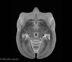
Flipped Brain After Half Way Transform (Coronal View)
Flipped Brain After Half Way Transform (Axial View)
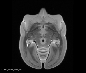
Original Brain After Half Way Transform (Coronal View)
Original Brain After Half Way Transform (Axial View)
Step 6: Generate the Symmetric Brain
Finally, we want to average the two “half way” transformed brain to generate the symmetric brain:
AverageImages 3 \
   T2WI_ex001_symmetric.nii.gz \
   1 \
   T2WI_ex001_warp_fwd.nii.gz \
   T2WI_ex001_warp_bck.nii.gz
The above command takes positional parameters as described below (in order, from left to right):
| Value | Explanation |
|---|---|
| 3 | This is the dimension, since we are working with 3D volumes, the dimension is 3. |
| T2WI_ex001_symmetric.nii.gz | This is the output file. |
| 1 | This is the flag to normalize input images. |
| T2WI_ex001_warp_fwd.nii.gz | Those are the half way transformed brains we calculated in Step 5. |
| T2WI_ex001_warp_bck.nii.gz |
Symmetric T2WI MRI Brain (Coronal View)
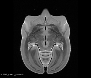
Symmetric T2WI MRI Brain (Axial View)
By following this guide, you have learnt how to make an asymmetric brain into an symmetric brain, this is useful when making a reference that represent brain structures in both hemisphere equally.
Last updated on 06-09-2023